
Overcurrent protection – protection used on almost all types of electrical equipment. This protection responds to an increase in the current flowing on the protected equipment.
We simulate the simplest protection, consisting of two stages:
- the first stage is a current cutoff;
- the second stage is a voltage controlled protection.
When modeling protection, we will use the library for modeling relay protection. Namely, we will need:
- Relays
- Trip delay
- Maximum / Minimum Filter
- Logical Elements
- Fourier Filter
As is known [1], current cutoffs are usually performed without delay. For the universality of the protection model, we introduce it.
We will make the second stage of the protection with control of the minimum phase voltage.
In fig. 1 shows the implementation of protection. The protection implementation is given in the attached file overcurrent_prot.mdl. Pay attention to the fact that the effective values of the observed currents and voltages are fed to the input of the protection model.

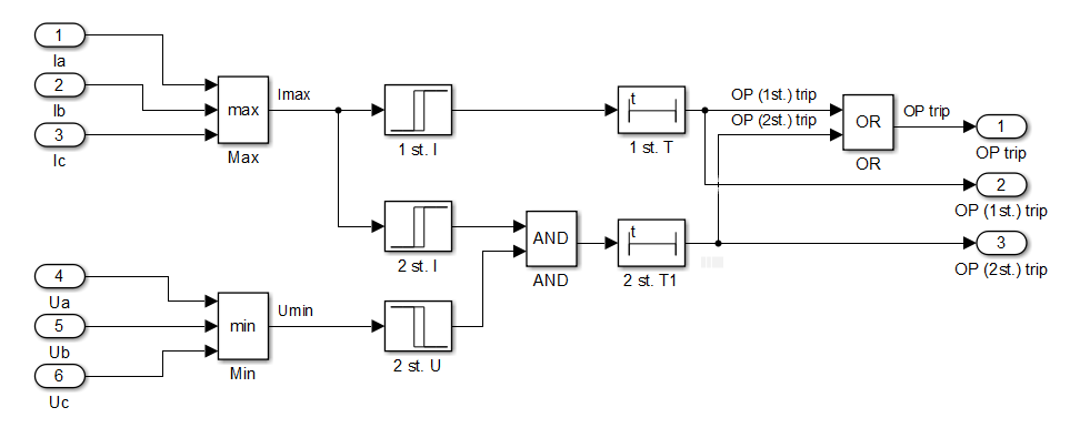
Fig. 1. Implementation of a two-stage overcurrent protection in Simulink
Attention! In order for the MTZ model to start, you must simultaneously open the library for modeling relay protection.
Test the resulting model. To do this, we will compose a model of a power line with one-way power supply. The model for testing protection is shown in Fig. 2.
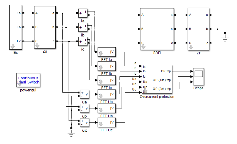
Fig. 2. Model for testing overcurrent protection
We calculate the settings of the protection. To do this, we simulate the load mode (for calculating the setpoint of the 2nd stage of the protection) and the three-phase short circuit mode at the end of the protected line (for calculating the setpoint of the 1st stage of the protection) in the attached model. We get the load current mode Iload = 600 A, the three-phase short-circuit current at the end of the protected line Isc = 1180 A. The settings are calculated simplified by multiplying the obtained current values by the reliability factor kr = 1.3. We get Itrip,1 = 1534 A, Itrip,2 = 780 A. We take the value of the minimum voltage relay setpoint to be equal to 70% of the nominal phase voltage Utrip,2 = 44 kV.
Set the rest of the settings obtained MTZ. The setting of the response time of the first stage of the MTZ Ttrip,1 will be equal to 20 ms, the second stage of Ttrip,2 will be equal to 420 ms.
We simulate a three-phase short circuit on the protected line. Because in the resulting circuit there is no feedback with the effect on the switch, then in some modes we must observe the operation of both stages. We simulate a three-phase short circuit at a distance of 25% of the line length. In fig. 3 presents the simulation results. We see that after the occurrence of a short circuit, the first stage is tripped with a delay of 20 ms after the moment the Fourier filter begins to show a current value greater than the setting, and then after 2 ms, the second stage is tripped.
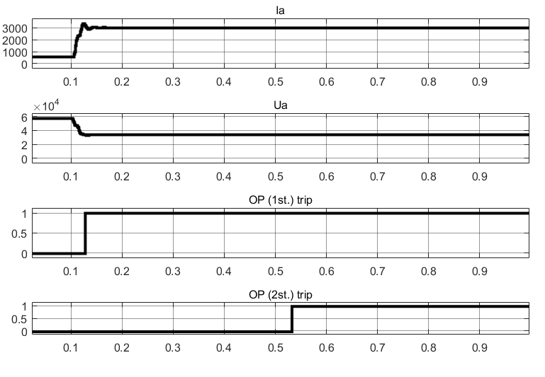
Fig. 3. Oscillogram of a three-phase short circuit
References
- Chernobrovov N.V., Semenov V.A. Releynaya zashchita energeticheskikh sistem. – M.: Energoatomizdat, 1998.