
In addition to the derivation of the method of nodal potentials, we consider a method for calculating electrical circuits using this method.
The calculation sequence is as follows.
- Number all nodes and set an arbitrary direction of currents in the circuit.
- Tighten the nodes with the same potential. The nodes will have the same potential if there is a clean branch with zero resistance between them – a short circuit (branches between nodes 2 – 4 and 3 – 5 in Fig. 1). It is not necessary to redraw the diagram with strained nodes, but then it should be noted that the potentials of the nodes at the ends of the short will be the same.
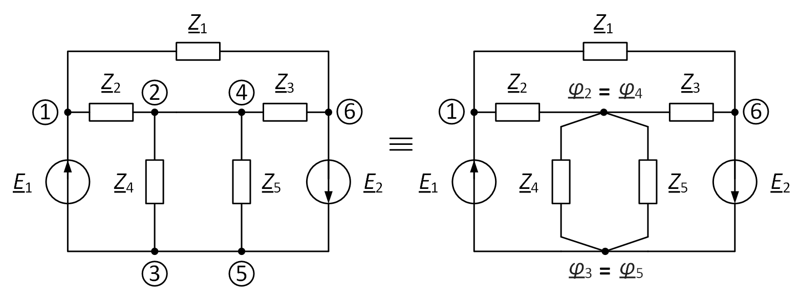
Fig. 1. An example of combining nodes with the same potential
- Choose a basis node (Fig. 2) and equate its potential to zero φ3 = 0 V. As a basis node, you can choose any, except when there are special branches. If there is at least one special branch in the circuit, then one of the ends of one of these branches should be taken as the base node. In this case, the potential of the other end will be equal to the input voltage φ1 = E1 if the voltage source is directed to this node, and equal to minus the input voltage φ6 = −E2 if the source is directed to the base node.
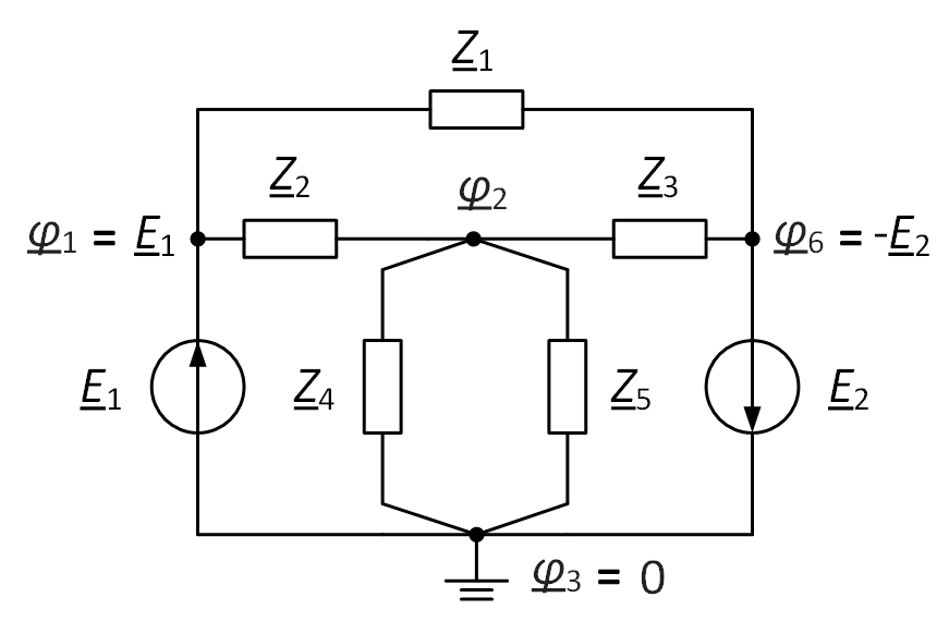
Fig. 2. The choice of the base node
Note. Often, the grounding symbol is used to designate the base unit, since it is commonly believed that the “ground” has zero potential.
- Compose equations for nodes without special branches whose potentials are unknown. The equations are written as follows:
- the potential of the node under consideration is multiplied by the sum of the conductivities of all branches adjacent to it;
- subtracted are the potentials of the nodes located at the opposite ends of adjacent branches, each multiplied by its own conductivity of the branch connecting them;
- equals the algebraic sum of the current sources and voltage sources adjacent to this node, the latter being multiplied by the conductivity of the branch in which they are located.
Under the algebraic sum is meant the need to take into account the direction of the sources, if the source is directed to the node in question, then it is written with a “+” sign, otherwise with a “-” sign.
If there is more than one special branch, and they do not have common nodes, then the equations for nodes that include a special branch that is not adjacent to the base node are written as follows:

- the potential of the node under consideration is multiplied by the sum of the conductivities of all the branches adjacent to it and the conductivities of the branches adjacent to the node of the opposite end of the special branch;
- the potentials of the nodes located at the opposite ends of the adjacent branches to the nodes of the special branch are subtracted, each multiplied by its conductivity of the adjacent branch;
- equals the algebraic sum of the current sources and voltage sources adjacent to the nodes of the special branch, the latter are multiplied by the conductivity of the branch in which they are located, with the exception of the voltage source of the special branch, which is multiplied by the sum of the conductivity of the branches adjacent to the node of the opposite end of the special branch.
- When compiling the equation, the conductivity of a particular branch is not taken into account (1/0 = ∞). It should also be borne in mind that the direction of the input voltage of a particular branch and, accordingly, its sign are taken into account relative to the node under consideration.
- Calculate the currents in the branches according to Ohm’s law as the algebraic sum of the potential difference and the voltage source in the branch with the desired current divided by the resistance of this branch. The potential in which the current is directed is deductible, and the voltage source sign is selected depending on the direction: in the case of co-direction with the current, the voltage source is taken with the “+” sign, otherwise with the “-” sign.
- The correctness of the calculation by the method of nodal potentials is easiest to check according to the first Kirchhoff law for unique nodes without special branches, substituting the obtained current values. Unique nodes are those nodes that, when considered, have at least one branch that is not adjacent to the other nodes considered.
Example. As an example, consider a circuit with two special branches and a current source (Fig. 3). The number of equations compiled to find the nodal potentials is
6 (total nodes) – 1 (base node) – 2 (node of special branches) = 3.
Arbitrarily designate nodes and currents in the circuit. One of the nodes of one of the special branches (1-4 and 3-6) is taken as the base, for example, node 4, in this case φ4 = 0, and φ1 = E1.
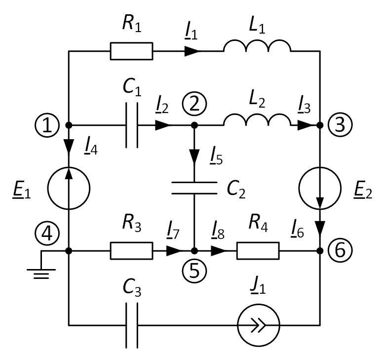
Fig. 3. An example of calculating an electrical circuit
In branch 3-6, it is necessary to find the potential of only one of the nodes (we calculate for node 6), since the second (potential of node 3) will differ by the EMF value, i.e. φ3 = φ6 – E2. Next, it is necessary to draw up equations for finding the remaining potentials at nodes 2, 5, and 6. It should be noted that the capacitance of the branch with the current source will not affect the calculations, since the conductivity of this branch is infinitely large, and the current is set by the source itself.
where
$$ {{\underline{Y}}_{1}}=\frac{1}{{{\underline{Z}}_{1}}}=\frac{1}{{{R}_{1}}+j\omega \cdot {{L}_{1}}}; $$
$$ {{\underline{Y}}_{2}}=\frac{1}{{{\underline{Z}}_{2}}}=-j\omega \cdot {{C}_{1}}; $$
$$ {{\underline{Y}}_{3}}=\frac{1}{{{\underline{Z}}_{3}}}=j\frac{1}{\omega \cdot {{L}_{2}}}; $$
$$ {{\underline{Y}}_{5}}=\frac{1}{{{\underline{Z}}_{5}}}=-j\omega \cdot {{C}_{2}}; $$
$$ {{\underline{Y}}_{7}}=\frac{1}{{{\underline{Z}}_{7}}}=\frac{1}{{{R}_{3}}}; $$
$$ {{\underline{Y}}_{8}}=\frac{1}{{{\underline{Z}}_{8}}}=\frac{1}{{{R}_{4}}}. $$
We substitute the known values of the potentials, reducing the number of unknowns:
We transfer all the free components to the right side of the equalities and obtain a finite system of equations with three unknown nodal potentials:
To solve a system of equations with unknown nodal potentials, you can use Matlab. To do this, imagine the system of equations in matrix form:
Let’s write a script in Matlab to find unknowns:
>> syms Y1 Y2 Y3 Y5 Y7 Y8 E1 E2 J1;
>> A = [Y7+Y5+Y8      -Y5      -Y8;
             -Y5 Y2+Y5+Y3      -Y3;
             -Y8      -Y3 Y8+Y3+Y1];
>> B = [             0;
        E1*Y2-E2*Y3;
E1*Y1+E2*(Y3+Y1)+J1];
>> fi=A\B
Note. To solve in a numerical form, it is necessary to replace the symbolic task of variables with real values of conductivities, voltage sources, and source current.
As a result, we obtain a column vector φ of three elements, consisting of the desired nodal potentials, while the currents in the branches through the potentials of the nodes:
$$ {{\underline{I}}_{1}}=\frac{{{\underline{\varphi }}_{1}}-{{\underline{\varphi }}_{3}}}{{{\underline{Z}}_{1}}}, $$
$$ {{\underline{I}}_{2}}=\frac{{{\underline{\varphi }}_{1}}-{{\underline{\varphi }}_{2}}}{{{\underline{Z}}_{2}}}, $$
$$ {{\underline{I}}_{3}}=\frac{{{\underline{\varphi }}_{2}}-{{\underline{\varphi }}_{3}}}{{{\underline{Z}}_{3}}}, $$
$$ {{\underline{I}}_{5}}=\frac{{{\underline{\varphi }}_{2}}-{{\underline{\varphi }}_{5}}}{{{\underline{Z}}_{5}}}, $$
$$ {{\underline{I}}_{7}}=\frac{{{\underline{\varphi }}_{4}}-{{\underline{\varphi }}_{5}}}{{{\underline{Z}}_{7}}}, $$
$$ {{\underline{I}}_{8}}=\frac{{{\underline{\varphi }}_{5}}-{{\underline{\varphi }}_{6}}}{{{\underline{Z}}_{8}}}, $$
where
φ3 = φ6 – E2.
To verify the accuracy of the calculation, you can use the equations according to the first Kirchhoff law: if the sums of currents in nodes 2 and 5 are equal to zeros, then the calculation is performed correctly:
I5 + I3 – I2 = 0,
I5 + I7 – I8 = 0.
So, the method of nodal potentials allows you to calculate fewer complex equations for calculating the electrical circuit in comparison with other methods with fewer nodes in comparison with the number of circuits.