
In a previously published article, an option was presented to calculate the frequency of an electrical signal from a transition through zero. This article provides an example implementation of a frequency filter.
In fig. 1 shows a model of an electric signal frequency filter implemented in Simulink. The implementation of this filter is given in the attached file calc_freq.mdl. The instantaneous value of the electrical signal is applied to the input of the frequency filter model.
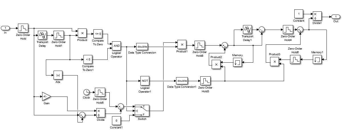
Fig. 1 Implementing a zero-pass frequency filter in Simulink
Test the resulting filter. For this we will use the circuit shown in Fig. 2.
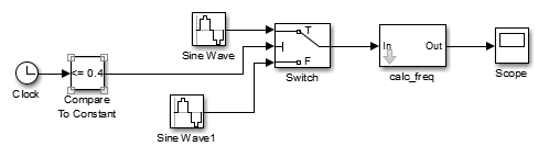
Fig. 2 Scheme for checking the operation of the frequency filter
At the first moment, a signal with a frequency of 50 Hz is supplied to the input of the frequency filter, from a moment in time t = 0.4 s a signal with a frequency of 48 Hz is supplied.

In fig. 3 shows the result of the frequency filter.
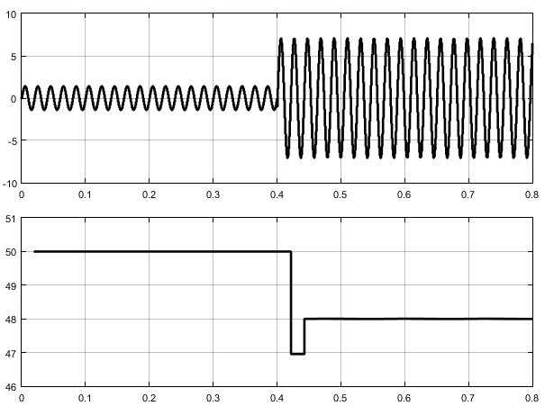
Fig. 3 The initial signal and the result of calculating the frequency of this signal
So, we simulated and tested the frequency filter.