Using modern software tools, such as Matlab / Simulink, can significantly simplify the analysis of various complex systems. Matlab scripts allow you to automatically run Simulink schemes with changing various parameters.
Such a problem may appear, for example, when constructing the amplitude-frequency characteristic of a filter. If the filter is quite complex, then its analytical description is not always possible. In this case, resort to numerical methods of analysis.
Simulink allows you to represent the filter in question as a set of elements of which it consists, and simulate its operation when a certain input signal, for example, voltage, is supplied to it.
It is known that the frequency response is a characteristic that describes the amplitude of the output signal depending on the input signal at different frequencies. That is, for its construction it is necessary to change the frequency of the input signal at a constant amplitude and measure the amplitude of the output signal. This is an iterative procedure that can be automated.
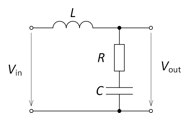
Consider the simplest filter shown in Fig. 1. Filter parameters R = 1 Ohm, L = 10 mH, C = 400 μF.

Fig. 1. The investigated filter

To construct the frequency response, with a known amplitude of the input voltage Vin, measure the amplitude of the output voltage Vout at various frequencies of the input voltage and form a measurement
A = Uвых / Uвх.
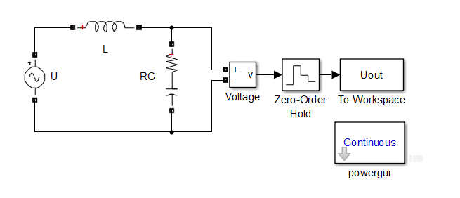
To do this, the circuit shown in Fig. 2 is assembled in Simulink. The model itself in Simulink: circuit.mdl.

Fig. 2. The circuit in Simulink to build the frequency response of the filter
Thus, the circuit of Fig. 2 it is necessary to run a certain number of times, while changing the frequency of the emf source and measuring the output voltage with a voltage voltmeter. To do this, use the following Matlab script (script in Matlab: simulink_start.m):
open('circuit.mdl'); % model's name
U_in = 100; % amplitude of input voltage source
U_out = []; % array for saving amplitude of output voltages
f = 0:1:500; % array of frequency of input voltage source
for k = 1:length(f)
    set_param('circuit/U','Frequency','f(k)'); % set parameter of voltage source
    sim('circuit'); % start simulation
    U_out = [U_out max(abs(Uout.signals.values(Uout.time>=1)))]; % add filtered output values to array of output voltage
end
plot(f,U_out/U_in,'k-') % plot figure with amplitude-frequency characteristic
grid on
hold on
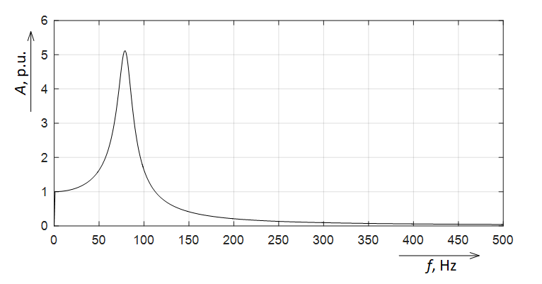
To automatically set parameters for model elements in Simulink, Matlab uses the set_param function. To start the simulation, use the sim function. After the script is finished, the frequency response is shown in Fig. 3.

Fig. 3. Frequency response of the investigated filter
So, the article presents an example of using model launch in Simulink using a script in Matlab to build an frequency responce of filter.