
The part of the network diagram, about which only general parameters are known, is modeled using an equivalent power system. In the phase coordinate method, the equivalent power system is modeled by the resistances in the direct and zero sequence and by the voltage source.
The equivalent circuit of the three-phase power system is shown in Fig. 1. It is given by the resistances along the straight and zero sequences, as well as the equivalent voltage source.
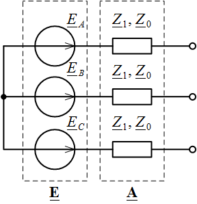
Fig. 1. Equivalent power system equivalent circuit
In a symmetric three-phase system, the phase emf vectors are displaced relative to each other by 120 °. Taking into account possible regulation, the equivalent voltage source matrix E by the phase coordinate method will be determined by the expression

where U is the rated voltage of the network (linear or phase, acting or amplitude); k – voltage regulation coefficient; δ – angle of power transmission.
The equivalent direct transmission matrix of the equivalent power system is determined based on the resistance in the direct and zero sequence according to the following expressions
![]()
where

Z1, Z0 – resistance of the equivalent system in a direct and zero sequence, respectively.
The attached file contains the calculation of the matrix form A and voltage of the equivalent power system in Matlab: A_eqsys.m