
In addition to the previous article, we will consider an example of compiling a network model with isolated neutral. Consider the simplest power line with one-way power supply (Fig. 1). It is necessary to draw up a power transmission model that will give out currents and voltages at the beginning of the line in short circuit modes and in single-phase earth fault modes.
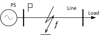
Fig. 1. Consider an isolated neutral power line
As already mentioned, the main difficulty in constructing a network model with isolated neutral is that it is necessary to take into account the nonzero value of the potential at neutral points in the damage mode.
In fig. 2 shows the network diagram according to Fig. 1 described using the phase coordinate method.
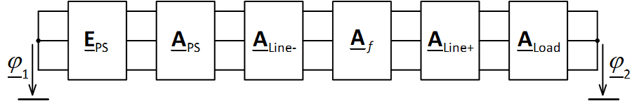
Fig. 2. An example of a circuit with isolated neutral in phase coordinates
Direct transfer matrices are calculated using the already known algorithms presented earlier:

- APS for power system model;
- ALine- and ALine+ for power line model;
- Af for short circuit model;
- ALoad for load model.
Scheme Fig. 2 can be represented in the form of an equivalent circuit (Fig. 3). The equivalent forward matrix is defined as
Aeqv = APS ∙ ALine- ∙ Af ∙ ALine+ ∙ ALoad.
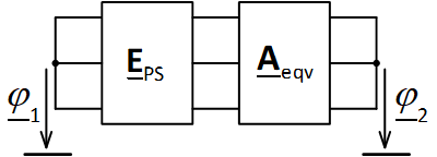
Fig. 3. Equivalent network scheme
To calculate the network, it is necessary to transform the direct transfer matrix into a matrix of the form Y. The scheme of the transformed network is shown in Fig. 4. The accepted directions of currents are indicated there, and E1 = EPS.
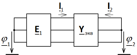
Fig. 4. Network diagram with an equivalent matrix of form Y
For this scheme we can write the equations
We represent the equivalent conductivity matrix in the form
Then the equations of the scheme can be represented as
where from
Given that the sum of the currents at the nodes is zero, we add the rows of the obtained matrix equations and simplify the equations. As a result, we obtain an expression for calculating the potentials of points
where  ,
, ![]() – sum of all matrix elements Ykj,
– sum of all matrix elements Ykj, ![]() – the sum of the elements of the matrix rows.
– the sum of the elements of the matrix rows.
After calculating the potentials, the sought currents and voltages are determined.
The calculation of the considered network with isolated neutral in the Matlab environment is given in the attached file example_isolated_grid.m.