
The phase coordinate method allows you to simulate networks with isolated neutral. In Russia, networks of 6-10-35 kV (sometimes 110 kV) operate with isolated neutral. Such networks are accompanied by small currents and significant overvoltages during single-phase earth faults.
The difference between networks with isolated neutral from the point of view of modeling is that it is necessary to take into account the nonzero value of the potential of neutral points in the damage mode.
In fig. 1 shows an example of an isolated neutral power system described using the phase coordinate method.
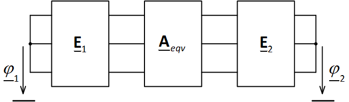
Fig. 1. An example of a circuit with isolated neutral in phase coordinates
When calculating currents and voltages for various types of damage, nonzero potentials φ1 and φ2 are taken into account in systems voltages.
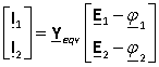
For the calculation of networks with isolated neutral it is most convenient to use equations of the form Y (Fig. 2). When calculating the boundary conditions are additionally taken into account.

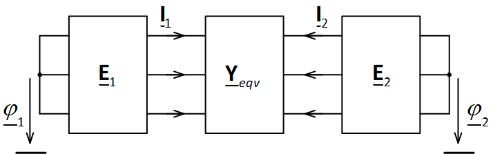
Fig. 2. An example of a circuit with isolated neutral in phase coordinates
Given that according to the first law of Kirchhoff, the sum of the currents in the node is zero, for the circuit of Fig. 2, we can write the following equations:
 ,
,
![]() ,
, ![]() .
.
Thus, in order to calculate unknown currents, it is first necessary to calculate the potentials of the points taking into account the boundary conditions, and only then determine the currents themselves.