
In almost any simulated circuit there is a power line. The phase coordinate method allows you to simulate the power line, including with distributed parameters, taking into account the longitudinal active and capacitive conductivity.
Fig. 1 shows a line equivalent circuit with distributed parameters.
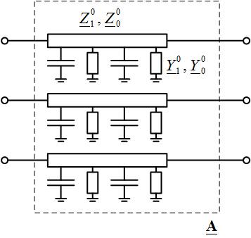
Fig. 1. The equivalent circuit of a power line with distributed parameters
In addition to longitudinal resistivities in both positive ![]() and zero sequence
and zero sequence ![]() , due to the material and location of the wires of the power line, the phase coordinate method takes into account specific conductivities
, due to the material and location of the wires of the power line, the phase coordinate method takes into account specific conductivities ![]() and
and ![]() (positive and zero sequence, respectively). The active component of conductivity takes into account losses on the corona, losses on melting ice and losses on leakage currents; capacitive occurs due to the charging currents of the power line.
(positive and zero sequence, respectively). The active component of conductivity takes into account losses on the corona, losses on melting ice and losses on leakage currents; capacitive occurs due to the charging currents of the power line.
To calculate the direct transmission matrix A of the power line, an auxiliary matrix is first compiled according to the expression
![]()

where
The direct transmission matrix is determined by the expression
A = exp(Dl),
where l is the length of the power line. The exp function in this case denotes the matrix exponential.
The attached file contains the calculation of the matrix A of the power line in Matlab: A_line.m