
In the phase coordinate method for modeling damage in the power line, the corresponding damage model is used with its transmission matrix. The damage model is composed of a set of active resistances.
In fig. 1 shows a fault model for short circuits. The model allows simulating symmetric three-phase K(3) and asymmetric single-phase K(1), interphase K(2) and two-phase K(1,1) earth faults. In this case, the active resistances vary in the range from 0 to ∞.
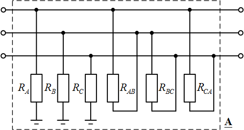 Fig. 1. Power line fault model
In the table 1 shows the resistance variations for different types of damage.
Tab. 1. Resistance values for different types of short circuits
| Type | RA | RB | RC | RAB | RBC | RCA |
| KA(1) | RA | ∞ | ∞ | ∞ | ∞ | ∞ |
| KB(1) | ∞ | RB | ∞ | ∞ | ∞ | ∞ |
| KC(1) | ∞ | ∞ | RC | ∞ | ∞ | ∞ |
| KAB(2) | ∞ | ∞ | ∞ | RAB | ∞ | ∞ |
| KBC(2) | ∞ | ∞ | ∞ | ∞ | RBC | ∞ |
| KCA(2) | ∞ | ∞ | ∞ | ∞ | ∞ | RCA |
| KAB(1,1) | RA | RB | ∞ | RAB | ∞ | ∞ |
| KBC(1,1) | ∞ | RB | RC | ∞ | RBC | ∞ |
| KCA(1,1) | RA | ∞ | RC | ∞ | ∞ | RCA |
| K(3) | RA | RB | RC | ∞ | ∞ | ∞ |
The direct transmission matrix A is determined by the expression
![]()

where

RA, RB, RC, RAB, RBC, RCA – resistances of the damage model (transient resistances at the point of short circuit).
The attached file contains the calculation of the matrix A of the damage model form in Matlab: A_fault.m