
A differential relay is used in the implementation of the basic protections of various equipment: generators, transformers, power lines, etc. The use of a relay with a braking characteristic prevents the non-selective action of the protection.
Two measurements are applied to the input of a differential relay with braking: differential and braking currents. There are many options for implementing braking current measurement, and they depend on the manufacturer of the relay protection device. Examples of the formation of braking current are given in [1].
Consider the braking characteristic of the differential relay presented in Fig. 1 [1].
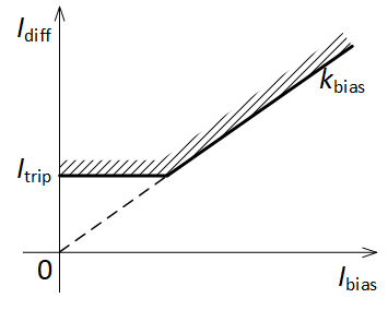
Fig. 1. Braking characteristic of the differential relay
Presented in fig. 1, the braking characteristic is described by two equations of lines, one of which is parallel to the abscissa axis, and the other passes through the origin. It follows that their task requires only two settings: the differential current setting Itrip and the braking coefficient kbias. The operation of a differential relay with braking occurs while the following conditions are met:

It should be noted that this relay, like ordinary maximum and minimum action relays, has a return coefficient kres, therefore, for a differential relay, it is also necessary to set it. Thus, the expressions describing the action of the differential relay with braking, are as follows:
where y[k] is the output value of the relay at a discrete time instant k, y[k-1] – output value of the relay at the previous time.
A variant of the implementation of the presented differential relay with braking in Simulink is given in the attached file biased_diff_relay.mdl. The type of circuit is shown in Fig. 2.
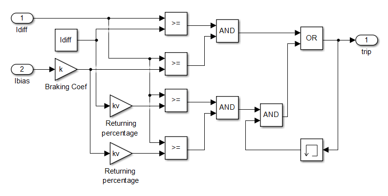
Fig. 2. Implementation of a differential relay with braking in Simulink
Test the resulting relay. For this we will use the circuit shown in Fig. 3.
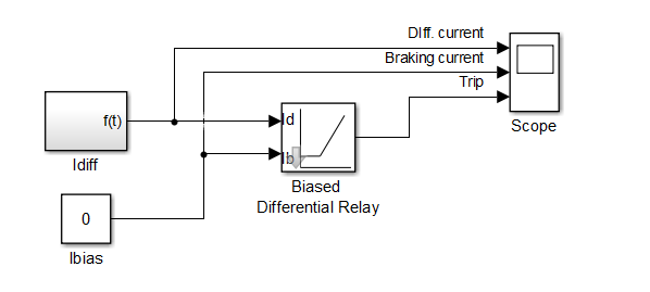
Fig. 3. Scheme for testing differential braking relays in Simulink
Set the relay settings Itrip = 1, kbias = 0.5, kres = 0.85. At the input we will supply a variable differential current with constant braking current. Check the correct operation of the relay and its return coefficient.
First, we apply a zero braking current. In fig. 4 shows the results of the relay. We see the relay actuation at Idiff = 1 and the relay return at Idiff = 0.85. A return ratio is provided.
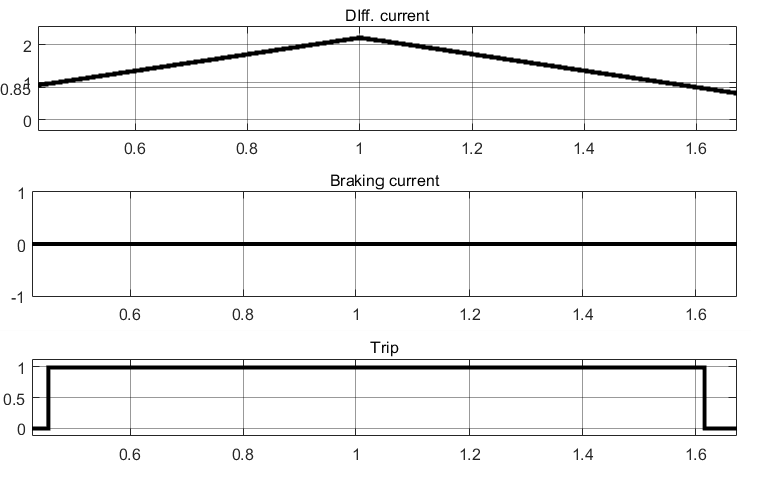
Fig. 4. Results of testing a differential relay with zero braking current
We apply a braking current of 4 A. In Fig. 5 shows the results of the relay. We see the operation of the relay at Idiff = 2 and the return of the relay at Idiff = 1.7. Check the correct operation of the relay. We calculate the expected value of the differential current required for the relay to operate at the indicated value of the braking current:
Idiff,trip = kbias ∙ Ibias = 0,5 ∙ 4 = 2 А.
Thus, the relay operates correctly. A return ratio is also provided.
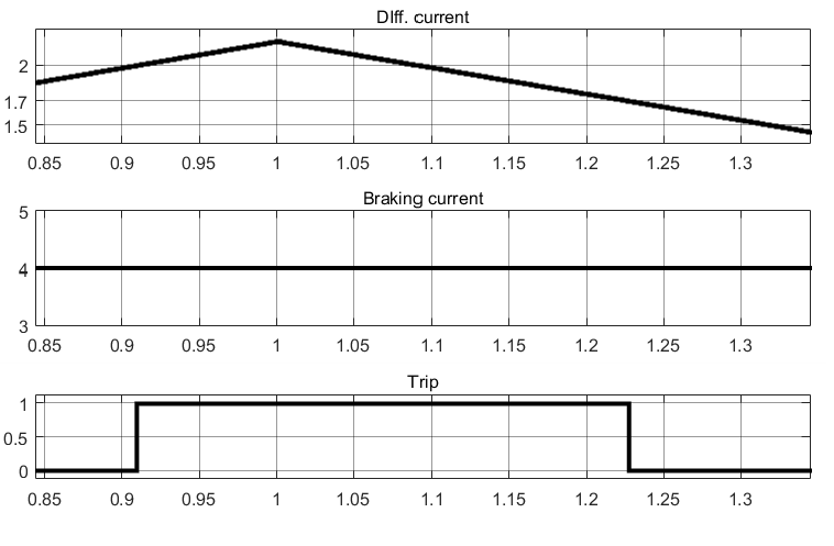
Fig. 5. Results of testing a differential relay with non-zero braking current
References
- Shneyerson E.M. Tsifrovaya releynaya zashchita. – M.: Energoatomizdat, 2007.