
Time delays are one of the main elements in modeling relay protection. They allow not only to create a delay in the operation of the protection, but, on the contrary, to extend the action of relay protection.
The following main types of time delays can be distinguished:
- trip delay, which passes the triggered state to the output after a predetermined time T (time delay actuation parameter or setpoint) only if the input signal maintains a tripped state for a time exceeding the setpoint;
- reset delay, which retains the triggered state at the output for a time T specified by the setpoint after the input signal returns to the idle state;
- pulse delay, which forms the tripped state at the output during the time T specified by the setpoint after the input signal transitions to the tripped state.
There are also various inverse time delays, accumulating time delays, etc.
The effect of time delays will be clearly shown during further testing of the model in Simulink. To test the time delays, a model scheme delays.mdl was created (Fig. 1).
When creating models, we used standard time delay models from the Simulink library Simscape \ SimPowerSystems \ Specialized Technology \ Control & Measurements \ Logic, where the following elements are located:
- On Delay – trip delay;
- Off Delay – reset delay;
- Monostable – pulse delay.
All time delays are set to T = 300 ms.

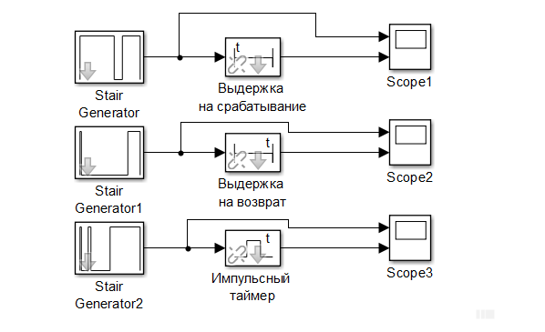 Fig. 1. Model for testing time delays
In fig. 2 presents the simulation results of the trip time delay. An input spasmodic signal is output. The duration of pulses 1 and 3 does not exceed the specified setting, therefore, at the output of the time delay (signal from below), the signal of the triggered state is not formed. The duration of pulse 2 exceeds the preset setting, therefore, at the output of the time delay, the signal of the triggered state is generated, and the duration of the output signal in the triggered state is determined by the time difference between the duration of pulse 2 and the time delay setting for operation.
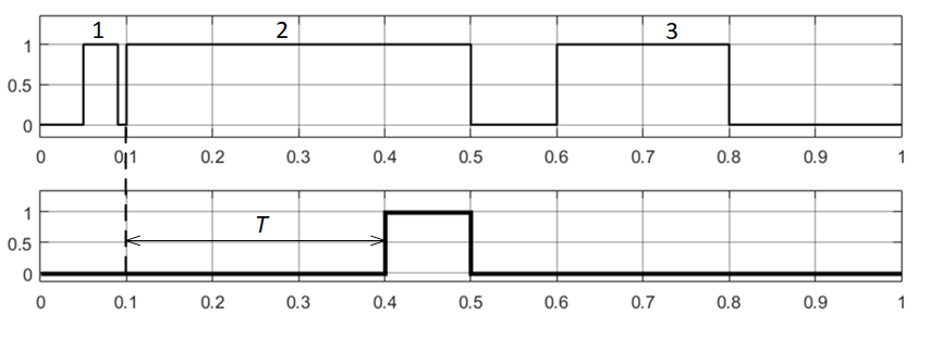 Fig. 2. The simulation results for trip delay
In fig. Figure 3 presents the simulation results of the reset time delay. An input spasmodic signal is also supplied. After each change of the input pulse from 1 to 0 (that is, when a “falling edge” of the signal appears), the delay time for the return generates a pulse of duration T (the set delay time for the return), and the delay time for the return also passes the input signal to the output . Thus, due to the fact that the time difference between the disappearance of pulse 1 and the appearance of pulse 2 does not exceed the specified setting, a continuous signal is observed at the output of the delay time for the operation until the pause exceeds the setting.
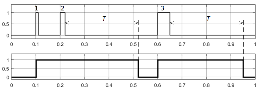
Fig. 3. The simulation results for reset delay
In fig. 4 presents the simulation results of a pulsed time delay. The pulse time delay upon the appearance of the input signal in the triggered state generates a pulse at the output of length T, determined by the setpoint. Moreover, if during the formation of the output pulse from the time delay, a new pulse arrives at the input, then it is ignored (for example, pulse 2 in Fig. 4). If the duration of the input signal exceeds the preset setting, then the pulse signal of duration T will still be observed at the output of the pulse time delay (see the result of the action of pulse 3 in Fig. 4).
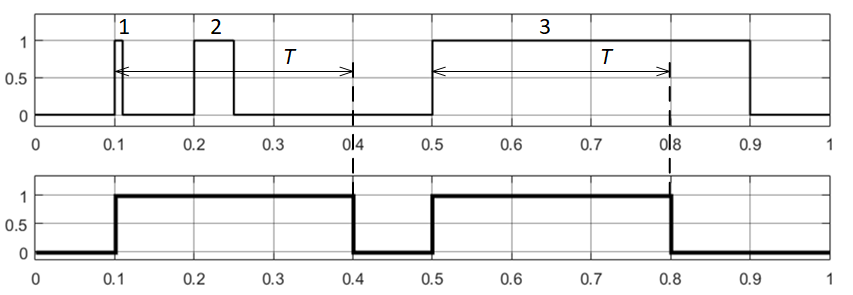
Fig. 4. The simulation results for pulse delay
So, Simulink using the standard library allows you to simulate time delays. The test results showed the features inherent in each type of time delay.