
Impedance relay is another type of relay used in relay protection. The difference of this relay is that it is a relay with two input quantities, and its operation is determined by the input value (measurement) falling into a certain response characteristic. The measurement in this case is the complex resistance Z.
Allocate a large number of impedance relays with various response characteristics [1]:
- with a circular characteristic (Mho), including offset;
- with elliptical characteristic;
- with polygonal characteristic (Quad), etc.
In this article, we will consider an example of the implementation of a impedance relay with a circular characteristic with an offset in Simulink. First, we give a mathematical description of this characteristic. The characteristic itself is shown in Fig. 1. It should be noted that the center of the characteristic is located on the line of maximum sensitivity (this is a line passing through the center of coordinates at an angle of maximum sensitivity φ).

Fig. 1. Characteristic of a impedance relay with a circular characteristic with an offset
The impedance relay is mainly used as a minimum relay. This type of impedance relay has several settings:

- trip setting Ztrip, Ohm;
- offset setting Zoffset, Ом;
- angle of maximum sensitivity φ, degrees;
- the return coefficient kres, which determines the return of the relay to an idle state (characteristic indicated by a dashed line in Fig. 1).
The relay is tripped when a measurement hits the characteristic indicated in fig. 1 by a solid line, and the relay returns upon subsequent departure of the measurement from the characteristic indicated in Fig. 1 dashed line. To determine the response conditions of the relay, we note on the response characteristic the center of the characteristic Z0 and its radius R (Fig. 2).
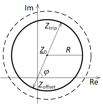
Fig. 2. Characteristic of the impedance relay with the specified center and radius
The relay is tripped when the condition is true
![]()
where Z – relay input impedance measurement, Z0 – coordinate of the center of the characteristic; R – radius of characteristic.
Thus, in order to simulate this impedance relay, it is necessary to determine the coordinate value of the center of the characteristic Z0 and the value of its radius R. Taking into account the fact that the center of the characteristic is located on the maximum sensitivity line leads to the following equations:
![]()
where values Ztrip and Zoffset are determined by the following equalities:
![]()
![]()
where Ztrip, Zoffset, φ – relay settings.
The relay is returned when the measurement leaves the response characteristic, which differs only in a large radius with the center of the characteristic unchanged (Fig. 1). To implement the return characteristic, it is enough only to multiply the value of R by the return coefficient kres.
A impedance relay with a circular characteristic with an offset is implemented in Simulink in the attached file circle_impedance_relay.mdl. The type of circuit is shown in Fig. 3. Note that additional logic, such as taking into account the current of accurate operation of the relay, etc., is not considered in this example.
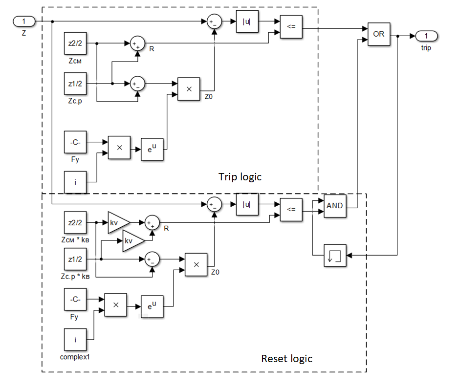
Fig. 3. Implementation of a impedance relay with a circular characteristic in Simulink
We test this relay using Z measurement, in which the angle is constant and equal to the maximum sensitivity angle. The relay settings are set as follows: Ztrip = 100 Ом, Zoffset = 50 Ом, φ = 75°, kres = 1,05. In fig. 4 shows the type of circuit for testing.
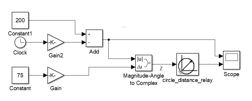
Fig. 4. Simulation scheme for testing a impedance relay
In fig. 5 shows the input metering module and the result of the operation and return of the impedance relay.
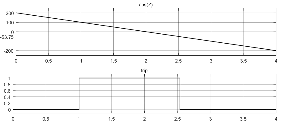
Fig. 5. Impedance relay test results
References
- Chernobrovov N.V., Semonov V.A. Releynaya zashchita energeticheskikh sistem. – M.: Energoatomizdat, 1998.