
Relay is the main element in modeling relay protection. A relay is a non-linear element that changes its output value in steps with a certain change in the input quantity.
Depending on the nature of the change in input values, 2 types of relays are distinguished:
- maximum action when the relay trips when exceeding the input value of a certain tripping parameter (or setting)
- minimum action when the relay is triggered when the input value drops below a certain setting
A distinctive feature of the relay is that the relay is returned from the tripped state to the initial one not at the setting value, but at the value determined by the return coefficient. The return coefficient is determined by the following expression:
 ,
,
where V is the input quantity, Vres is the value of the input quantity at which the relay returns from the tripped state to the initial one, and Vtrip is the relay setting.
The value of the return coefficient for the relay of maximum action is less than 1, and for the relay of minimum action more than 1.

To simulate relay protection, Simulink has a special Relay element responsible for the relay, therefore its implementation is very simple (Fig. 1).
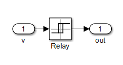
Fig. 1. Relay implementation in Simulink
Test the relay. To do this, a circuit for checking the maximum and minimum relays is assembled in Simulink in attached file max_min_relay.mdl (Fig. 2). For both relays, the trip value is Vtrip = 1. The return coefficient for the maximum action relay (element “max” in Fig. 2) is set equal to 0.95; for the minimum action relay (element “min” in Fig. 2) is set equal to 1.05.
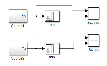
Fig. 2. Scheme for testing the maximum and minimum relay
In fig. Figure 3 shows the result of operation of the maximum action relay (element “max” in Fig. 2). The results show that the relay is triggered when the input value is 1, which coincides with the setting value. The relay returns when the value of the input value is 0.95, which coincides with the value of the relay return, determined by the expression
![]()
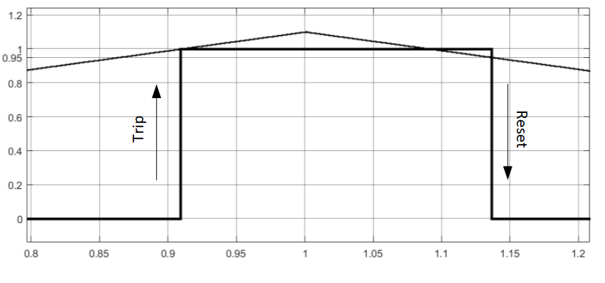
Fig. 3. Result of operation and return of the maximum relay
In fig. Figure 4 shows the result of the operation of the minimum-action relay (element “min” in Fig. 2). The results show that the relay is triggered when the input value is 1, which coincides with the setting value. The relay returns when the value of the input value is equal to 1.05, which coincides with the value of the relay return, determined by the expression
![]()
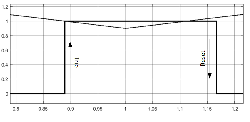
Fig. 4. Result of operation and return of the minimum relay
So, in Simulink there is a standard relay element that correctly describes the dependence of the output signals on the input.