
When implementing relay protection algorithms, RS flip-flops are often used. A RS flip-flops is a nonlinear element whose output signal can be in one of two stable states depending on the input signals. The most commonly used RS flip-flop has 2 inputs: S – set (to set the output value) and R – reset (to reset the output value).
The RS flip-flop retains its previous state when a zero signal is applied to both inputs of the trigger, and changes it when a single signal is applied to one of the inputs. In this case, when a single signal is input to input S, a single signal will also be observed at the output, and when a single signal is input to input R, a zero signal will be output. In the event that single signals are applied to both inputs, the output signal depends on the priority with which this RS flip-flop is executed. The dependence of the output signal Q on the input signals S and R is given in tab. 1.
Tab. 1. The dependence of the output signal from the input signals for the RS flip-flop
| S | R | Q for trigger with priority S | Q for trigger with priority R |
| 0 | 0 | 0 | 0 |
| 1 | 0 | 1 | 1 |
| 0 | 1 | 0 | 0 |
| 1 | 1 | 1 | 0 |
Simulink has a standard “Bistable” block, which is an RS flip-flop with selectable input priority. We will test this element using the attached circuit in Simulink rs_trigger.mdl. Note that this element has 2 outputs – Q and! Q, where the second output is the inverted first output. The type of circuit is shown in Fig. 1.
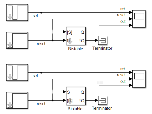
Fig. 1. Scheme for testing RS flip-flop in Simulink
In fig. 2-3 show the results of testing RS flip-flops with different input priorities. The results obtained completely coincide with the dependence given in table. 1.

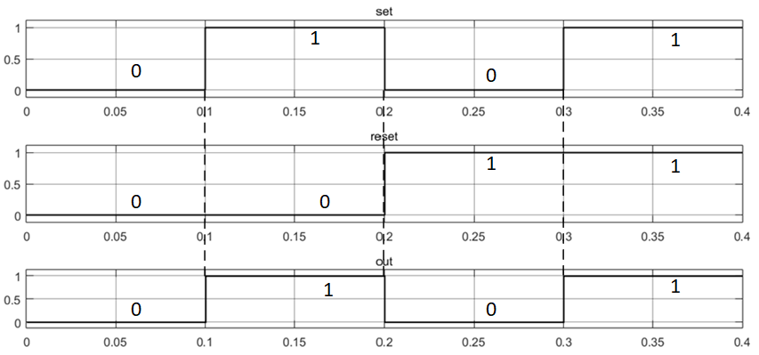
Fig. 2. Test results of RS flip-flop with input priority S
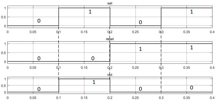
Fig. 2. Test results of RS flip-flop with input priority R
The use of RS flip-flops in relay protection devices allows avoiding, for example, the bounce of relay contacts, when for a short period of time the relay either trips or returns. We simulate the bounce of relay contacts using a pulse generator (Fig. 4). In fig. Figure 5 shows the output from the RS flip-flop. We see that the output signal from the trigger is constant and does not depend on a change in the input signal supplied to input S.
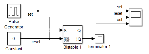
Fig. 4. The circuit for modeling the bounce of relay contacts
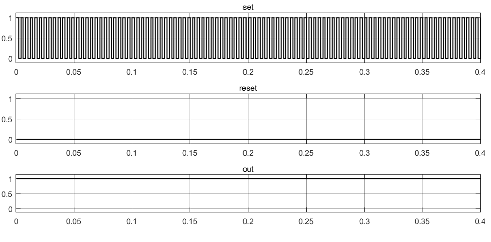
Fig. 5. Test results of the RS flip-flop with relay bounce