
When buiding vector diagrams for three-phase circuits, the choice of a base vector is now available. When choosing a vector as the base one, its angle is taken equal to 0°, and the angles of the remaining vectors are counted relative to it.
The base vector is selected in the drop-down menu (Fig. 1).
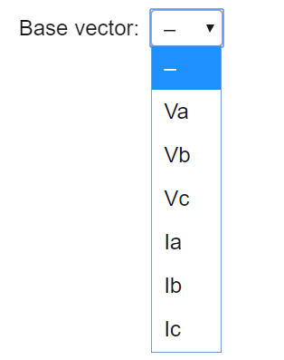
Fig. 1. The choice of the base vector
By default, the base vector is not selected, and the vector diagram is built from the source data.
The number of possible options for the base vector in the drop-down menu depends on the selected checkboxes (Fig. 2). With both U and I checkboxes selected, the menu is shown in Fig. 1.
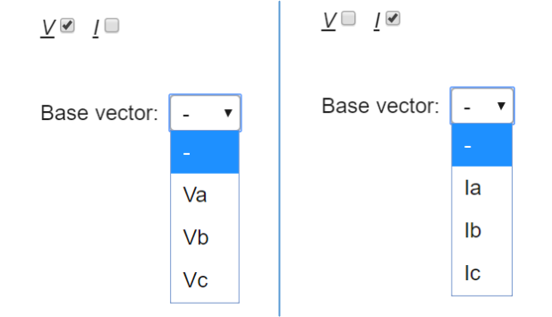
Fig. 2. Variants of choosing a base vector depending on the selected checkboxes

After setting the base vector and clicking the Build button, a vector diagram for the source data is displayed depending on the selected base vector. In fig. Figure 3 shows an example with the base vector Ua not selected (Fig. 3a) and with the accepted base vector Ic (Fig. 3b).
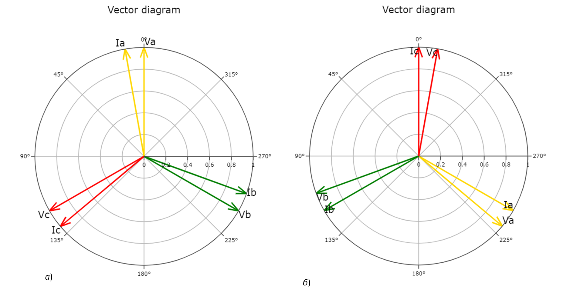
Fig. 3. Vector diagram depending on the selected base vector