Input data
To build a vector diagram, it is necessary to set the voltages and currents in polar form. For this appropriate fields are provided (Fig. 1). The angle of voltages and currents are set in degrees.
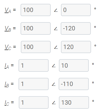
Fig. 1. Input data setting
To build a vector diagram only for currents or only for voltages, you must select the appropriate checkbox parameters (Fig. 2).
![]()
Fig. 2. Selecting data to display
After setting all the parameters, you must click the “Display” button, as a result of which a vector diagram for the given values will be displayed (Fig. 3). All values are displayed in relative units. For the base value for voltages and for currents the maximum of the three specified voltages and currents are taken.
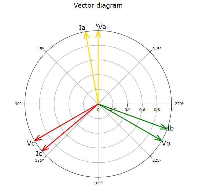
Fig. 3. Vector diagram
Base vector
When constructing a vector diagram, a choice of a basic vector is available (Fig. 4). When choosing a vector as the base one, its angle is taken equal to 0 °, and the angles of the remaining vectors are counted relative to it.
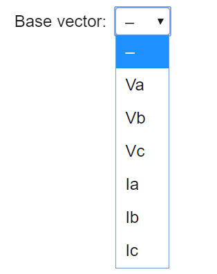
Fig. 4. The choice of the base vector
Only the data selected for display by checkboxes appears in the drop-down list (Fig. 2).
Tools
For vector diagrams analysis tools are available: increase / decrease graph, display values. The results can be exported to a picture in png format.