Appointment
The program is designed to calculate steady-state modes of electrical circuits according to the Ohm law and Kirchhoff’s rules. The program allows you to draw a circuit, set the parameters of its elements and calculate the circuit. As a result, a textual description of the calculation procedure is formed.
Circuit drawing
Drawing a diagram is performed by dragging elements using drag-and-drop from the sidebar and connecting the selected elements. The following elements with configurable parameters are available in the sidebar:
- resistor
 :
:- element number;
- resistance, Ohm;
- capacitor
 :
:- element number;
- impedance, Ohm;
- inductor
 :
:- element number;
- impedance, Ohm;
- voltage source
 :
:- element number;
- peak value, V;
- initial phase, °;
- current source
 :
:- element number;
- peak value, A;
- initial phase, °.
When you hover the mouse pointer over an element, the connection points of the element with other elements (Fig. 1) and a buttons for deleting and rotating the element (Fig. 2) are displayed.
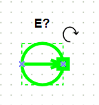
Fig. 1. Element connection points
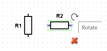
Fig. 2. Element rotation and deletion buttons
To connect one element to another, you need to move the mouse pointer over the connection point of the element, press the left mouse button and connect it to another element (Fig. 3) by clicking the left mouse button on the connection point of another element.
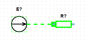
Fig. 3. Elements connection
Nodes are formed automatically when you connect an element to another connector line.
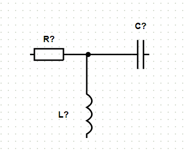
Fig. 4. Node forming
When you click on an element a window with the element’s parameters is formed on the right side of the screen. Parameters that are available for editing (Fig. 5).
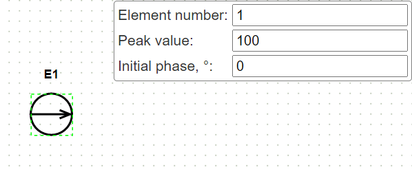
Fig. 5. Element parameters editing
Limitations when drawing a diagram
For the correct analysis of the circuit, the connecting line must be connected on both sides to the elements / connecting lines, otherwise the program will not calculate the circuit, which it will signal with the appropriate notification.
Saving a circuit as a file and loading a schematic from a file
On the sidebar there are a button ![]() for loading a circuit from file and a button
for loading a circuit from file and a button ![]() for saving the circuit to file.
for saving the circuit to file.
Setting parameters
For capacitors and inductors their impedances are set.
If for capacitor there is information about it capacitance, then that impedance is calculated by formula
$$ X_{C} = \frac{1}{2 \pi f C}, $$
where f − frequency, C − capacitance.
If for inductor there is information about it inductance, then that impedance is calculated by formula
$$ X_{C} = 2 \pi f L, $$
where f − frequency, L − inductance.
Setting the parameters of voltage and current sources are set in the form of their module and phase. For example, if in the original data
$$ \underline{E} = 3 + 4j, $$
then in order to set this value in the program, it must be converted to polar form. We get:
$$ \underline{E} = 5 \angle 53.13 \degree $$
Thus, in the “Peak value” field we set the value 5 and in the “Initial phase” field set the value 53.13.
Calculation methods
After completion of drawing the circuit, pressing the “Calc.” button starts the calculation of the electrical circuit. The program analyzes the original circuit and reports any errors if any errors are found. In case of successful analysis of the circuit, the calculation is started.
It should be noted that if the calculated circuit is single-circuit, then the calculation will be performed according to Ohm’s law.
After completing the calculation, the program checks the power balance and build current and voltage vector diagrams.
Ohm’s law calculation
Example:
Input data:
- E1:
- Element number: 1
- Peak value: 100
- Initial phase, °: 0
- R1:
- Element number: 1
- Resistance, Ohm: 1
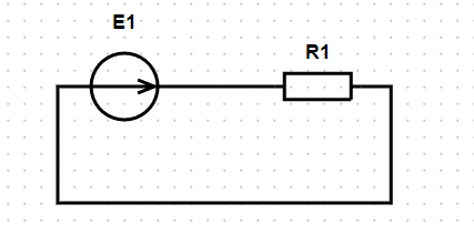
After pressing the “Calc.” button, a solution is formed:
There is only one loop in the original circuit. Let’s calculate it according to Ohm’s law.
According to Ohm’s law, the current in a closed circuit is equal to the ratio of the voltage source of the circuit to the resistance. Let us compose an equation, taking for the positive direction of the current $ I $ the direction of the voltage source $ E_{1} $:
$$ R_{1}\cdot I = E_{1} $$
Put values of resistances and sources into the resulting system of equations and get:
$$ 1.0\cdot I=100 $$
Hence, the sought current in the circuit is
$$ I = 100\space \textrm{A} $$
Check the power balance.
Define the power consumed by the receivers: $$ S_\textrm{c} = R_{1}⋅|I_{1}|^{2}. $$
Put the numerical values and get: $$ S_\textrm{c} = 1⋅100^{2}=10000. $$
Define the power given by the sources: $$ S_\textrm{s} = S_{E} + S_{J}, $$
where $ S_{E} $ – power given by voltage sources, $ S_{J} $ – power given by current sources.
Define the power $ S_{E} $, given by voltage sources: $$ S_{E} =E_{1}⋅ I’_{1} , $$
where $ I’ $ means conjugate complex current.
Put the numerical values and get: $$ S_\textrm{E} = 100⋅100=10000. $$
Because there are no current sources in the circuit, then $$ S_{J} = 0. $$
The power given by all sources is equal to: $$ S_\textrm{s} = S_{E} + S_{J} =10000+0=10000. $$
Thus, $ S_\textrm{c} = 10000 $, $ S_\textrm{s} = 10000 $. The power balance is observed.
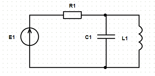
Kirchhoff’s rules calculation
Example:
Input data
- E1:
- Element number: 1
- Peak value: 100
- Initial phase, °: 0
- R1:
- Element number: 1
- Resistance, Ohm: 1
- L1:
- Element number: 1
- Impedance, Ohm: 1
- C1:
- Element number: 1
- Impedance, Ohm: 1
After pressing the “Calc.” button, the accepted designations of the nodes and the accepted directions of currents are displayed on the original circuit, and a solution is formed:
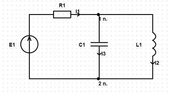
Calculate the circuit according to Kirchhoff’s rules.
Circuit parameters: nodes quantity – 2, branches quantity – 3, independent loops quantity – 2.
Arbitrarily set the directions of currents in branches and direction of bypassing loops.
Accepted directions of currents:
Current $ \underline{I}_{1} $ directed away from node ‘2 n.’ to node ‘1 n.’ through elements $ \underline{E}_{1} $, $ R_{1} $.
Current $ \underline{I}_{2} $ directed away from node ‘1 n.’ to node ‘2 n.’ through elements $ L_{1} $.
Current $ \underline{I}_{3} $ directed away from node ‘1 n.’ to node ‘2 n.’ through elements $ C_{1} $.
Accepted directions for bypassing loops:
Loop №1 bypasses through elements $ \underline{E}_{1} $, $ R_{1} $, $ L_{1} $ in the specified order.
Loop №2 bypasses through elements $ L_{1} $, $ C_{1} $ in the specified order.
Compose equations according to current Kirchhoff’s law. When drawing up the equations, the currents flowing into the node will be taken with the “+” sign, and the “outgoing” ones – with the “-” sign.
Number of equations compiled according to current Kirchhoff’s law is $ N_\textrm{n}- 1 $, where $ N_\textrm{n} $ is the number of nodes. For this scheme, the number of equations according to the current Kirchhoff’s law is 2 – 1 = 1.
Define an equation for node №1:
$$ \underline{I}_{1}- \underline{I}_{2}- \underline{I}_{3} = 0 $$
Compose the equations according to voltage Kirchhoff’s law. When drawing up equations, positive values for currents and voltage sources are selected if they coincide with the direction of the loop bypass.
The number of equations compiled according to voltage Kirchhoff’s law is $ N_\textrm{b}- N_\textrm{n} + 1 $, where $ N_\textrm{b} $ is the number of branches without current sources. For this scheme, the number of equations according to the voltage Kirchhoff’s law is 3 – 2 + 1 = 2.
Define an equation for loop №1:
$$ R_{1}\cdot \underline{I}_{1}+jX_{L1}\cdot \underline{I}_{2}=\underline{E}_{1} $$
Define an equation for loop №2:
$$ jX_{L1}\cdot \underline{I}_{2}-(-jX_{C1})\cdot \underline{I}_{3}=0 $$
Combine equations into one system, while transferring the known quantities to the right side, leaving only the components with the sought currents in the left side. The system of equations according to Kirchhoff’s laws for the original circuit is as follows:
$$ \begin{cases}\underline{I}_{1}- \underline{I}_{2}- \underline{I}_{3} = 0 \\ R_{1}\cdot \underline{I}_{1}+jX_{L1}\cdot \underline{I}_{2} = \underline{E}_{1} \\ jX_{L1}\cdot \underline{I}_{2}-(-jX_{C1})\cdot \underline{I}_{3} = 0 \\ \end{cases} $$
Put the values of impedance and sources into the resulting system of equations and get:
$$ \begin{cases}\underline{I}_{1}- \underline{I}_{2}- \underline{I}_{3}=0 \\ \underline{I}_{1}+ j \cdot \underline{I}_{2}=100 \\ j \cdot \underline{I}_{2}+ j \cdot \underline{I}_{3}=0 \\ \end{cases} $$
Further solve the system of equations and get the required currents:
$$ \underline{I}_{1} = 0\space\textrm{A} $$
$$ \underline{I}_{2} =-100j\space\textrm{A} $$
$$ \underline{I}_{3} = 100j\space\textrm{A} $$
Check the power balance.
Define the power consumed by the receivers:
$$ \underline{S}_\textrm{c} = R_{1}⋅|\underline{I}_{1}|^{2}+jX_{L1}⋅|\underline{I}_{2}|^{2}- jX_{C1}⋅|\underline{I}_{3}|^{2}. $$
Put the numerical values and get:
$$ \underline{S}_\textrm{c} = 1⋅0^2+1j⋅((-100)^{2})-1j⋅(100^{2})=0. $$
Define the power given by the sources:
$$ \underline{S}_\textrm{s} = \underline{S}_{\underline{E}} + \underline{S}_{\underline{J}}, $$
where $ \underline{S}_{\underline{E}} $ - power given by voltage sources, $ \underline{S}_{\underline{J}} $ – power given by current sources.
Define the power $ \underline{S}_{\underline{E}} $, given by voltage sources:
$$ \underline{S}_{\underline{E}} =\underline{E}_{1}⋅ \underline{I}’_{1} , $$
where $ \underline{I}’ $ means conjugate complex current.
Put the numerical values and get:
$$ \underline{S}_\textrm{\underline{E}} = 100⋅0=0. $$
Because there are no current sources in the circuit, then
$$ \underline{S}_{\underline{J}} = 0. $$
The power given by all sources is equal to:
$$ \underline{S}_\textrm{s} = \underline{S}_{\underline{E}} + \underline{S}_{\underline{J}} =0+0=0. $$
Thus, $ \underline{S}_\textrm{c} = 0 $, $ \underline{S}_\textrm{s} = 0 $. The power balance is observed.
Support
If it is impossible to calculate the scheme, please inform the Site Administration by e-mail support@faultan.ru.