
The power direction relay is used in the implementation of directional protections, which allow for operation only with a certain power direction in a certain network operation mode.
Typically power direction relays are used with the response characteristic shown in Fig. 1 [1].
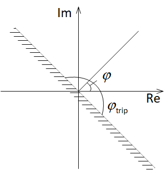
Fig. 1. Characteristic of power direction relay
The shown in Fig. 1 relay has 2 settings: maximum sensitivity angle φ and the width of the zone φtrip. Accounting for the minimum value of current and voltage when calculating power is assumed outside the logic of this relay.
The relay responds to the value of the input metering angle of the complex power S. The relay is tripped when the condition is true
![]()

When implementing this condition in Simulink, it is necessary to take into account that the standard element for calculating the phase gives the value of the angle of the complex number in the range from –π to π. In this regard, certain difficulties arise when implementing a relay, which has no restrictions when setting its settings.
We assume that the maximum sensitivity angle can be set in the range φ from 0° to 360°, and the width of the zone does not exceed 180°. When implementing a relay, in addition to the above, the following conditions must be taken into account:
- if
 , than if
  , then the input of the relay is measured power angle
  ;
; - if
 , then it is necessary to subtract 360°.
An embodiment of the power direction switch in Simulink is given in the attached file power_direction_relay.mdl. The type of circuit is shown in Fig. 2. The value of the integrated power is supplied to the relay input.
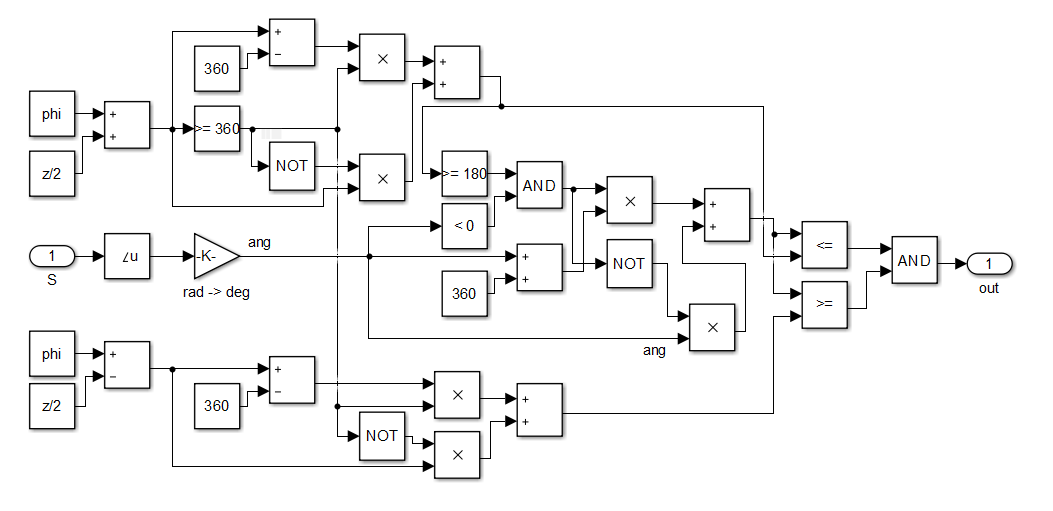
Fig. 2. Implementation of power direction relay in Simulink
Test the relay. For this we will use the circuit shown in Fig. 3.
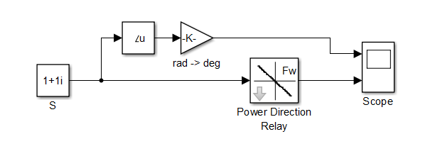
Fig. 3. Scheme for testing inverse time delay in Simulink
We will change the power value at the input of the relay and check the operation. Set the relay settings φ = 45° and φtrip = 180°. In fig. Figure 4 shows the results of triggering the power direction relay at various values of the input power.
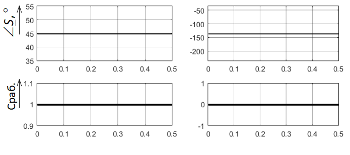
Fig. 4. Test Results for Power Direction Relay
Set the relay settings φ = 225° and φtrip = 180°. In fig. Figure 5 shows the results of triggering the RNM at various values of the input power.
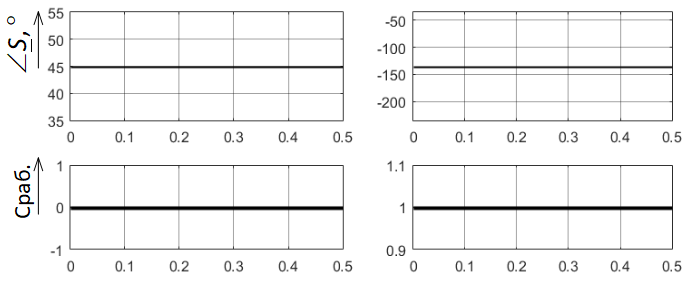
Fig. 4. Test Results for Power Direction Relay
References
- Shneyerson E.M. Tsifrovaya releynaya zashchita. – M.: Energoatomizdat, 2007.